Mechanical Design > Sketcher
Select Start > Mechanical Design > Sketcher from the menu bar. Alternative: Select File > New and select Part from the list.
 or
or 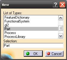
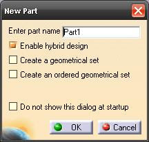
Enter Part name and click OK. You'll enter the Part Design Workbench.
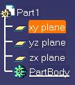
Select a reference plane in the geometry area.
 or
or 
Click on the Sketch icon or select Insert > Sketcher > Sketch.
You will then enter the Sketcher Workbench.
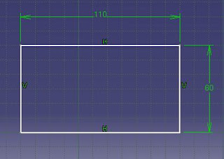
Then click on the Rectangle icon (or any profile as you please). Alternative: Insert > Profile > Predefined Profile > Rectangle. Click on any spot for a starting point and move the cursor to any position.
The dimension of the rectangle will be affected by the grid when the Snap to Point is activated.
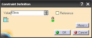
Adjust the dimensions by using the Constraint command. Click on the Constraint icon and select the line profile you want to adjust (Alt: Insert > Constraint > Constraint Creation > Constraint). A dimension profile will come out and double-click on the dimension profile and a Constraint Definition box will appear where you can adjust the value.
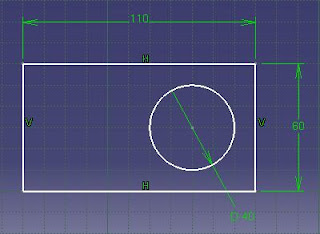
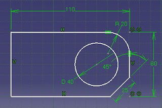
Create a circle in the rectangle. Click the Circle icon or select Insert > Profile > Circle > Circle. Click on any spot for the center of the circle and move the cursor to obtain a desired size. Resize the circle using the Constraint command.
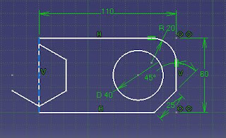
You should have something like this:
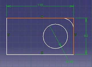
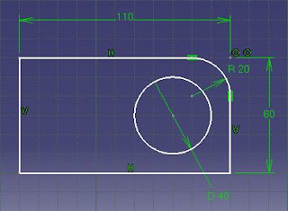
Creating a corner. Click on the Corner icon or select Insert > Operation > Corner. Select the horizontal and vertical lines on a corner and a curve will automatically appear. Click once again to create the corner. Some prompt may appear and click "Yes" on all of them. Once the corner is created, modify the dimension by double-clicking on the dimension constraint.
Note: If the drawing changed unexpectedly, try to fix some lines (right click on a line and select Line.X object > Fix.
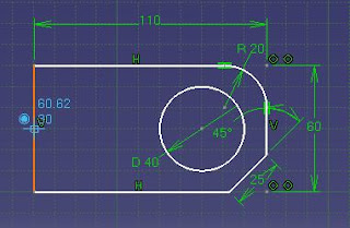
Create a Chamfer using the similar method of creating the Corner. You should obtain something like shown below.
Now create a hexagon using the Hexagon icon (click on the arrow below the Rectangle icon to pop up the Hexagon icon (Alt: Insert > Profile > Predefined Profile > Hexagon).
Click on the vertical line as shown and drag the cursor to obtain the hexagon.
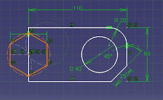
Resize the hexagon using the Constraint command and resize the circle around the hexagon.
Now we are going to trim the hexagon. Delete all the circles and constraint around the hexagon. Click the arrow below the Trim icon on the Operation toolbar or select . Drag the pop up toolbar to other place. You should now obtain the Relimitations toolbar.
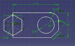
Now click on the Quick Trim icon and then click on all the line you want to remove. (Alt: Insert > Operation > Relimitations > Quick Trim).
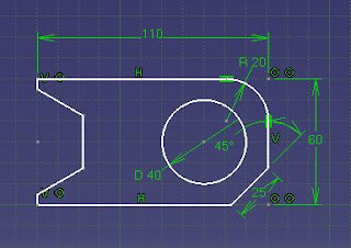
Now you have completed the drawing. Save the file and keep it for later use. You can click the Exit workbench icon to go to the Part Design workbench.
Select Start > Mechanical Design > Sketcher from the menu bar. Alternative: Select File > New and select Part from the list.
 or
or 
Enter Part name and click OK. You'll enter the Part Design Workbench.
Select a reference plane in the geometry area.
 or
or 
Click on the Sketch icon
 or select Insert > Sketcher > Sketch.
 You will then enter the Sketcher Workbench.
Then click on the Rectangle icon
 (or any profile as you please). Alternative: Insert > Profile > Predefined Profile > Rectangle. Click on any spot for a starting point and move the cursor to any position.
The dimension of the rectangle will be affected by the grid when the Snap to Point
 is activated.
Adjust the dimensions by using the Constraint command. Click on the Constraint icon
 and select the line profile you want to adjust (Alt: Insert > Constraint > Constraint Creation > Constraint). A dimension profile will come out and double-click on the dimension profile and a Constraint Definition box will appear where you can adjust the value.

Create a circle in the rectangle. Click the Circle icon
 or select Insert > Profile > Circle > Circle. Click on any spot for the center of the circle and move the cursor to obtain a desired size. Resize the circle using the Constraint command.
You should have something like this:

Creating a corner. Click on the Corner
 icon or select Insert > Operation > Corner. Select the horizontal and vertical lines on a corner and a curve will automatically appear. Click once again to create the corner. Some prompt may appear and click "Yes" on all of them. Once the corner is created, modify the dimension by double-clicking on the dimension constraint.
Note: If the drawing changed unexpectedly, try to fix some lines (right click on a line and select Line.X object > Fix.


Create a Chamfer
 using the similar method of creating the Corner. You should obtain something like shown below.
Now create a hexagon using the Hexagon
 icon (click on the arrow below the Rectangle icon to pop up the Hexagon icon (Alt: Insert > Profile > Predefined Profile > Hexagon).
Click on the vertical line as shown and drag the cursor to obtain the hexagon.


Resize the hexagon using the Constraint command and resize the circle around the hexagon.

Now we are going to trim the hexagon. Delete all the circles and constraint around the hexagon. Click the arrow below the Trim
 icon on the Operation toolbar or select . Drag the pop up toolbar to other place. You should now obtain the Relimitations toolbar.

Now click on the Quick Trim
 icon and then click on all the line you want to remove. (Alt: Insert > Operation > Relimitations > Quick Trim).

Now you have completed the drawing. Save the file and keep it for later use. You can click the Exit workbench
 icon to go to the Part Design workbench.
2 comments:
This is a very good guide, however after following it to the letter, when it comes to deleting the exterior lines around the hexagon. My original rectangle does not interset with it.
Therefore when I try to Quick Trim the middle part, of the left line of the Rectangle it just tries to delete the entire line. And for the life of me I cannot find how you make 2 seperate lines interact/merge.
Anon here - Scrap that last post, I closed CATIA, tried again later, and it all went well. Thank you for writing these.