This tutorial is about making weld joint in CATIA Weld Design Workbench.
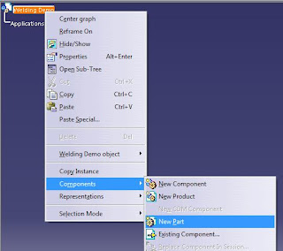
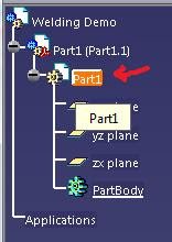
Go to the Weld Design Workbench (Start > Mechanical Design > Weld Design). Rename the product as Welding Demo. Right click on the product tree and create a new part (Right-click > Components > New Part). After the new part has been created, expand the part tree and double-click on the part name to go to the Part Design Workbench as shown in the figure.
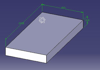
In the Part Design Workbench, create a rectangular bar of 100x50x10 mm dimension. Check my other blog entry if you don't know how to create the bar.
After finishing the bar or plate, double-click on the Welding Demo main product tree. This will automatically brings you back to the Weld Design Workbench.
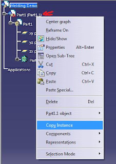
Now make another part just by copying the existing part. Right-click on the Part1 (Part1.1) instance and select Copy Instance. Then click on the Welding Demo parent tree. Automatically Part1 (Part1.2) will be created under the existing part in the tree.

The new part is exactly at the same position with the previous part. Use the manipulation tool or the compass to position them apart of each other.
The weld function is different than the assembly feature because you'll have to position the part correctly in order to successfully make the weld join. If the parts are not in the correct position, you'll be receiving error messages every time you want to make a joint.
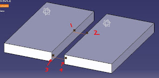
The first step is to assemble them using constraints. We'll use coincidence constraint to connect edges of the part before making the weld joint. Select the coincidence constraint and select edge 1 and 2 as shown in the figure below. Then create another coincidence constraint and connect edge 3 and 4 together.
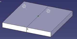
After pressing the update button, the parts should connect together as shown.
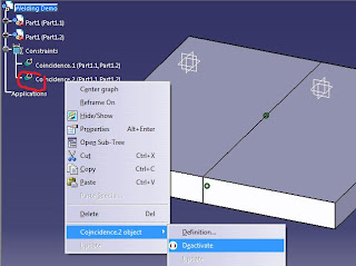
At this point, you still can't make a weld joint because some surfaces required as joint parameters are hidden after being constrained. A little trick is required here. First, fix the first part with the Fix Component constraint. Then expand the Constraints tree and deactivate constraint 2 (coincidence.2) that connects edge 3 and 4. Don't delete it. Then use the manipulation tool with the "with respect to constraints" is checked to move part 2 in the x direction just like as shown in the figure.
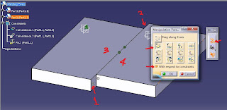
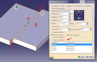
Now select the Single V-Butt Weld feature or Insert > V Butt Welds > Single V-Butt Weld. A box will appear for you to adjust the welding parameters. Change the height to 5mm, shape to convex with 0.5mm offset, and select surfaces as numbered in the figure above respectively. You can click on the Selection Assistant to help you select the surface in order. Press Enter or OK button to make your weld joint.

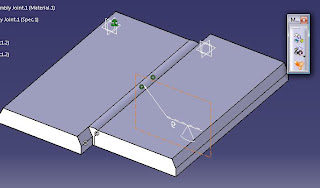
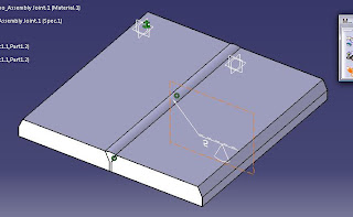
After that, reactivate constraint 2 (coincidence.2) and press the Update button, the parts will repositioned as before and you now have your weld joint.


7 comments:
hai,
bagus tutorial ni. we are in the same shoes.catia V5.hope we can connect each other.
www.mycatiav5.blogspot.com
how can I weld 2 tubes at 90 degrees on to each other?
great CATIA tutorial for welding design.
possible to weld 2 tube in a particular angle?
thanx ...was stuck here...m new but its intresting...
Hi.,
It was really useful for me.
Thanks for the great work.
Regards.,
Shreekantha
+919731512373
Nice Designs,I am aslo making some design wit Catia software.
you can here my work : catia v5 part design