The first step is to enter the Assembly Design Workbench and create a new product. Rename the product from Product1 to Universal Joint. Then by right-click on the product name, select Components > New Part. Rename the new part as Shaft. By double-clicking on the new part name you'll be redirected to the Part Design Workbench to model the first part.
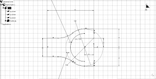
In the Part Design Workbench, select the yz-plane and click on the Sketcher Tool icon (or Insert > Sketcher > Sketch). In the Sketcher Workbench, create something as shown the the figure below:
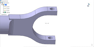
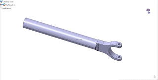
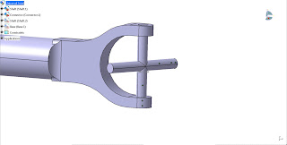
Then elongate the part with a 40mm diameter cylindrical shaft of about 300mm length. Then some make-ups with fillets will make the part look a little nicer. Create a 10mm diameter hole to insert the connector to the shaft as shown in the figure. Finish the part with more fillets.
Then double-click on the Universal Joint product to go back to the Assembly Design Workbench. Similar to the first step, insert a new part to the product and rename it as Connector (or anything else as you like). Double-Click on the Connector to model it in the Part Design Workbench.
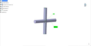
Create a T-cross with 10mm diameter to fit the hole of the shaft and 80mm length.
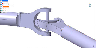
Back in the Assembly Design Workbench, duplicate the Shaft part by using the Fast Multi Instantiation function (Ctrl+D or Select the Shaft part and select Insert > Fast Multi Instantiation). Use the Manipulation tool to move the part to a proper location. Assemble the Shaft parts with the Connector part using the Coincidence Constraints.
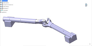
The Shafts and Connectors are rotating parts therefore we need a fixed part to anchor the shafts. Create another part to be a base for the shafts to rotate. I made a couple of blocks with 40mm groove to be assembled with the shafts. The blocks are distanced by 150 degrees angle.
After completing the blocks, fix the blocks using the Fix constraint and assemble them with the shafts using the Coincidence Constraint and try use the Manipulation tool to check if the assembly is correct. Check whether all the parts are moving as intended when the "With respect to constraints" are ticked.


8 comments:
Good CATIA tutorial, btw, do you know any good source of learning materials about CATIA?
Good CATIA tutorial, btw, do you know any good source of learning materials about CATIA?
Awesome tutorial. Keep up the good work!
Great blog! Would you be interested in being a guest blogger on my CAD Systems Help blog?
@NTW.. maybe I'll join you later because as for now I don't even have time to update my own blogs. Thank you for the offer and keep in touch please.
great tutorials
it is helping me a lot.
Please upload some more
terbaik.. tp klo dpt tnjuk cmne nk hasilkan drwing lg ok. sy bru blaja
@Anonymous.. There are videos in my youtube channel showing how to make a drawing. The problem is I still don't have a good video capture device that's why all my Catia videos are too fast.