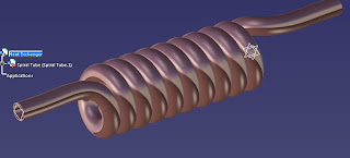
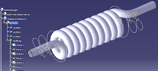
A heat exchanger will require at least 2 medium for heat transfer. For this model, the medium are 2 fluids. 1 is flowing through the spiral tube and another fluid flows outside the spiral tube in a closed chamber. Now we are going to make the chamber. Last time we stop was after modeling the spiral tube. As seen in the picture, I've set copper for the material property and adjusted
the rendering.
Now right click on the Parent tree and create a new part. Name the new part as Chamber. After a new part has been created, activate the Chamber design by double click on it and go to the Generative Shape Workbench (Start > Shape > Generative Shape Design). Make sure you are not creating a new part that is not in connection with the Heat Exchanger. If a Create New Part dialogue appeared, closed it reactivate the Chamber Part Tree.
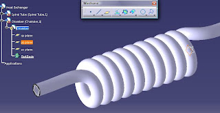
In my version, both Spiral Tube and Chamber shares the same origin. I dont want to change this because it will be helpful during the modelling of the chamber. By selecting the yz-plane, activate the Sketcher Workbench. Create a circle of slightly larger than the diameter of the spiral tube. I set is as 85 mm.
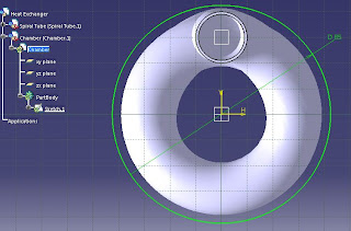
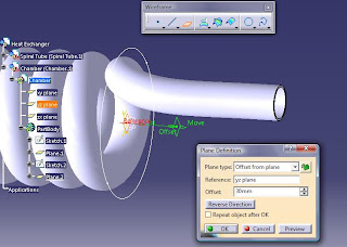
What to do next is to create more circles like this at other location and join them. Length of the helix was 200mm therefore i'll create another circle of similar dimension 200m apart respective to the yz-plane. Some additional planes are required to make those circles. For the 35mm diameter circle, the plane is 30mm from the yz-plane and the 28mm diameter circle is 20mm from the 35mm circle.
Then you should have something like this.
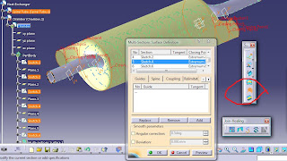
Then we are going to make a surface from these circles. Select the Multi-Section Surface tool (Insert > Surfaces > Multi-Section Surface) and select all 6 circles. Press Preview to view the generated surface.
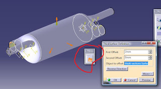
Done with that, we will have to generate solid part from the surface. For this, we will have to go to the Part Design Workbench. Select Start > Mechanical Design > Part Design without changing anything. Select the Thick Surface tool (or Insert > Surface-Based Features > Thick Surface) and select the generated Multi-Section Surface. Set the first offset to be 2mm that will make the solid generated outward and press OK. Now the Chamber complete.
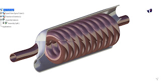
There are several holes needed to fit in the Spiral Tube but maybe you can do them later. Apply Steel material to the Chamber part and adjust the rendering property.

5 comments:
hello... hapi blogging... have a nice day! just visiting here....
i think u should create another hole for the fluid to enter the spiral tube
Nice tutorial. But how can you apply the material in assembly mode? The steel and copper material look doesn't appear in the assembly but they are there when I open the parts separately...
How did you get the last section view ?